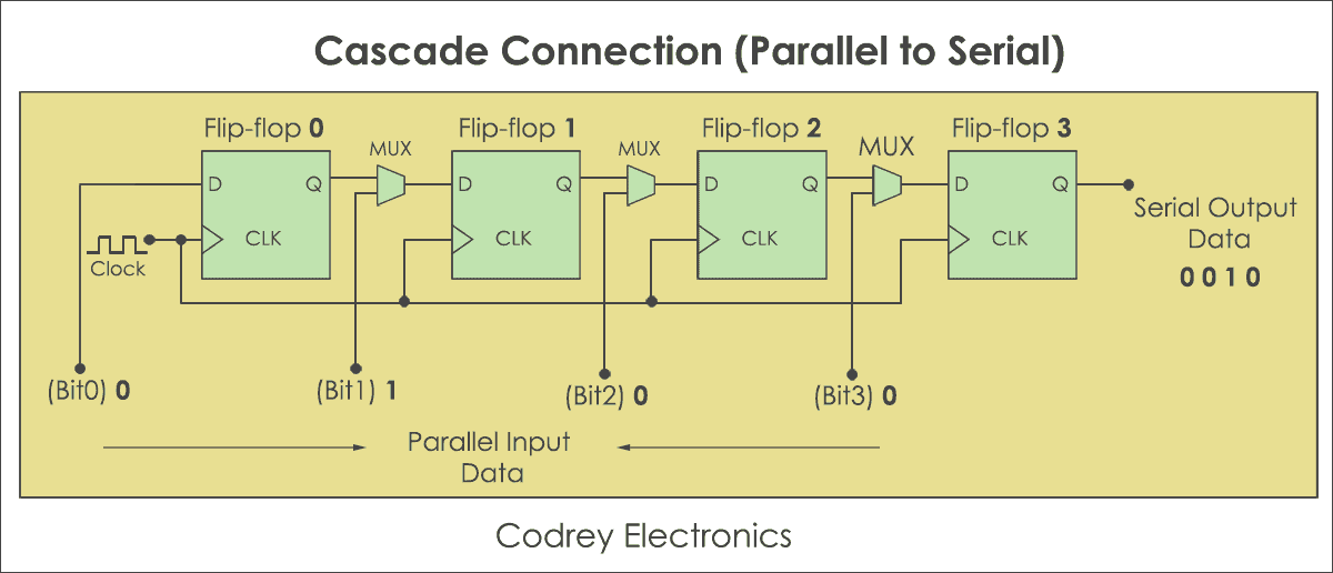

- BLOCK DIAGRAM OF PARALLEL TO SERIAL CONVERTER GENERATOR
- BLOCK DIAGRAM OF PARALLEL TO SERIAL CONVERTER FULL
It reads the data packet bit by bit and converts the received data into the parallel form to eliminate the three bits of the data packet. After receiving the parallel data from the bus, it forms a data packet by adding three bits like start, stop and parity. The data transmission of a UART can be done by using a data bus in the form of parallel by other devices like a microcontroller, memory, CPU, etc. In UART, the data transmission from Tx UART to Rx UART can be done asynchronously (there is no CLK signal for synchronizing the o/p bits). The flow of data will be from both the transmitting (Tx) & receiving (Rx) pins of the UARTs. For this, simply two cables are required to communicate between two UARTs. In this communication, there are two types of UARTs available namely transmitting UART and receiving UART, and the communication between these two can be done directly by each other. Typically, the baud rates of microcontrollers are 9600 to 115200. The baud-rate-generator among the transmitter and the receiver generates the speed that ranges from 110 bps to 230400 bps. A read (or) write control logic is used for telling when to read or write. The shift registers in transmitter and receiver move the bits to the right or left till a byte of data is transmitted or received. The hold register in the transmitter comprises the data-byte to be transmitted.
BLOCK DIAGRAM OF PARALLEL TO SERIAL CONVERTER GENERATOR
This generator is used for generating the speed when the transmitter section & receiver section has to transmit or receive the data. These two sections are commonly provided by a baud-rate-generator. Likewise, the receiver section includes a receive hold register, shift register, and control logic. The transmitter section includes three blocks namely transmit hold register, shift register and also control logic. The UART block diagram consists of two components namely the transmitter & receiver that is shown below. Parallel Communication UART Block Diagram The best examples for this communication are old printers, PCI, RAM, etc. Parallel data communication is expensive as well as very fast, as its requires additional hardware and cables. In parallel data communication, the data can be transferred through multiple cables at once. Thus, this communication is very useful in compound circuits compared with parallel communication. It requires very less circuitry as well as wires.

Serial data communication is not expensive when we compared with parallel communication. In serial data communication, the data can be transferred through a single cable or line in a bit- by- bit form and it requires just two cables. In UART, the communication between two devices can be done in two ways namely serial data communication and parallel data communication. The main function of UART is to serial data communication.
BLOCK DIAGRAM OF PARALLEL TO SERIAL CONVERTER FULL
The UART full form is “Universal Asynchronous Receiver/Transmitter”, and it is an inbuilt IC within a microcontroller but not like a communication protocol (I2C & SPI).


 0 kommentar(er)
